Target
Our target in this lesson will be Wesnoth 1.14.9.
Overview
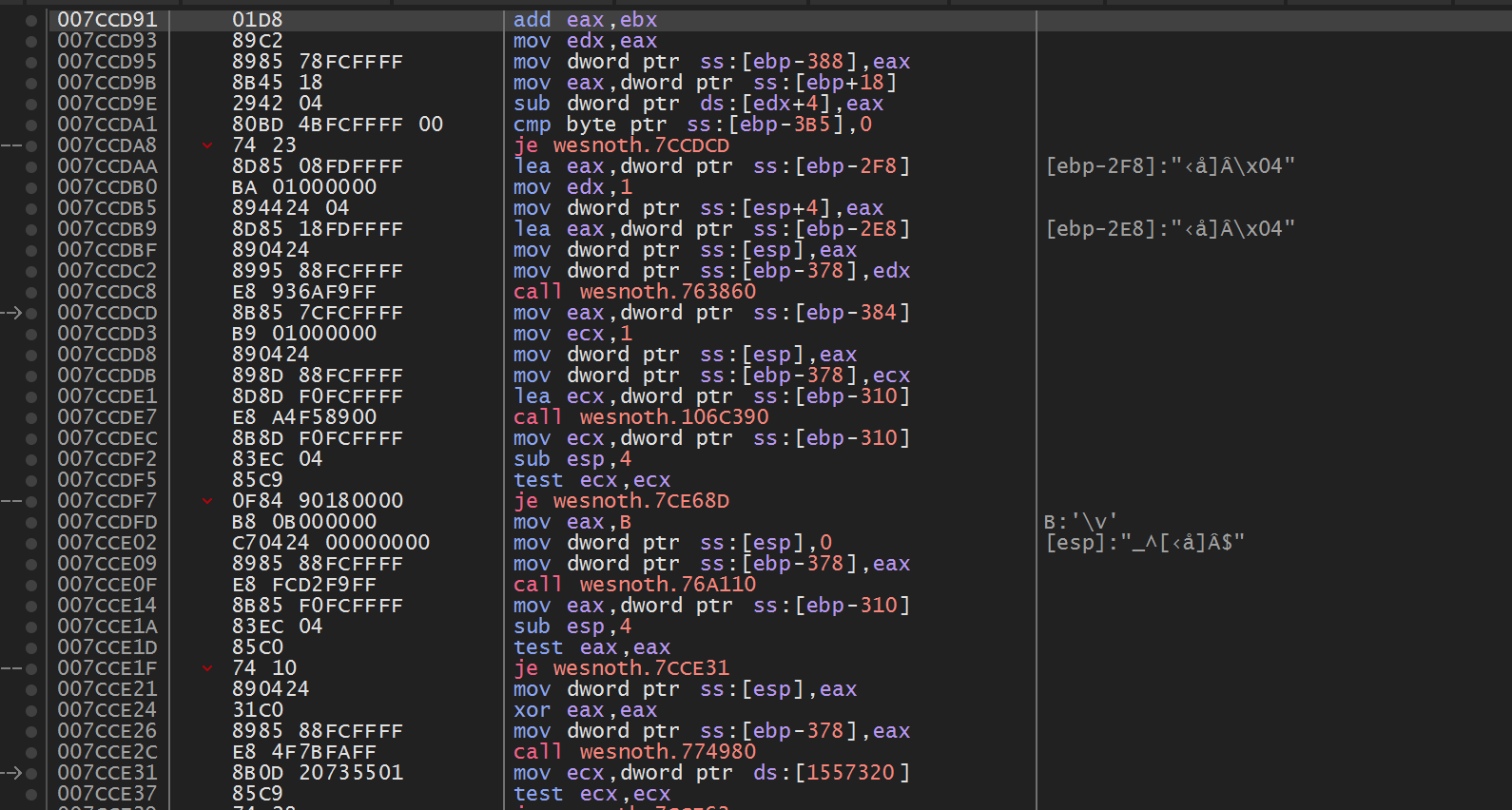
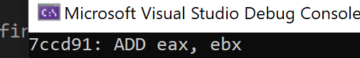
In previous lessons, we used x64dbg to debug and reverse games. When viewing these games in x64dbg, we are able to see the instructions that the games are executing. For example, we saw that the following instructions were responsible for decreasing a player’s gold when recruiting a unit in Wesnoth:
From the Pattern Scanner lesson, we know that these instructions are all stored as opcodes, which are byte values. The process of converting these opcodes to instructions is known as disassembly. In this lesson, we will cover how to create a limited disassembler.
The full source code discussed in this lesson is available on github.
Disclaimer
Writing a disassembler is a complex task that takes a large amount of time. Even supporting a single instruction set in an efficient way takes many weeks of reading specifications and implementation. The approach covered here should be used as a starting point, but with the caveat that the approach will not scale. The main goal for this lesson is to explain how these concepts work. For an example of a feature-complete disassembler, check out the Capstone Engine.
Instructions
For a CPU to understand and execute each opcode encountered, these opcodes
must have a consistent format. Each opcode must be assigned a specific
instruction. For example, we have seen from previous lessons that the opcode
0xE8 always represents a call instruction.
This mapping of opcodes to instructions is known as a processor’s
instruction set.
Each CPU can implement a unique instruction set. However, most Windows-based games are compiled with the expectation that they will be running on 32-bit, Intel-based processors. These processors typically implement a version of the x86 instruction set. For Intel processors specifically, this is referred to as IA-32.
The x86 instruction set is complex and has many different operations.
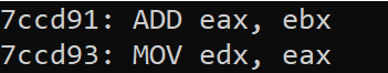
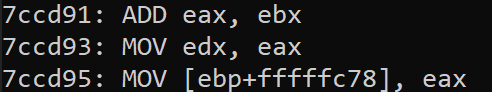
These operations can also be a different length. For example, in the
screenshot on the page above, we see that the
mov instruction on the second line
(0x7ccd93) is 2 bytes (0x89C2), whereas the
mov instruction on the third line is 6 bytes (0x8985 78FCFFFF). For the CPU to understand the length of the instruction, this data
must be encoded in the bytes in some way.
Instruction Set Reference
Imagine you want to create a compiler that will take the following C++ code and produce a binary that can run on an x86-compatible processor:
int x = 2;
This code could be converted into assembly in multiple ways, such as:
mov [x], 2
or
mov eax, 2
mov [x], eax
We have seen that there are multiple forms of the mov instruction, with different lengths. As the compiler developer, we need to know which form to use to produce our binary code.
To solve this problem, companies like Intel release instruction set references. These contain a full listing of all public instructions and their associated opcodes, along with other architectural information, such as how to encode the length of the instruction. The IA-32 reference is available here.
As we build our disassembler, we will use that reference to understand instructions. In addition, we will use another reference (here) to help figure out unknown opcodes and which instruction they are associated with.
Dumping a Process’s Opcodes
Like in the Pattern Scanner lesson, our target in this lesson will be Wesnoth. We will use the same code from that lesson to locate, attach, and read the game’s opcodes into a buffer:
int main(int argc, char** argv) {
  HANDLE process_snapshot = 0;
  HANDLE module_snapshot = 0;
  PROCESSENTRY32 pe32 = { 0 };
  MODULEENTRY32 me32;

  DWORD exitCode = 0;

  pe32.dwSize = sizeof(PROCESSENTRY32);
  me32.dwSize = sizeof(MODULEENTRY32);

  process_snapshot = CreateToolhelp32Snapshot(TH32CS_SNAPPROCESS, 0);
  Process32First(process_snapshot, &pe32);

  do {
    if (wcscmp(pe32.szExeFile, L"wesnoth.exe") == 0) {
      module_snapshot = CreateToolhelp32Snapshot(TH32CS_SNAPMODULE, pe32.th32ProcessID);

      HANDLE process = OpenProcess(PROCESS_ALL_ACCESS, true, pe32.th32ProcessID);

      Module32First(module_snapshot, &me32);
      do {
        if (wcscmp(me32.szModule, L"wesnoth.exe") == 0) {
          unsigned char* buffer = (unsigned char*)calloc(1, me32.modBaseSize);
          DWORD bytes_read = 0;

          ReadProcessMemory(process, (void*)me32.modBaseAddr, buffer, me32.modBaseSize, &bytes_read);

          // buffer contains the game's opcodes

          free(buffer);
          break;
        }

      } while (Module32Next(module_snapshot, &me32));

      CloseHandle(process);
      break;
    }
  } while (Process32Next(process_snapshot, &pe32));

  return 0;
}
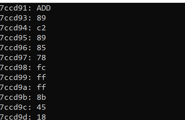
We will validate our disassembler on the same instruction set seen in the
beginning of this lesson (starting at the address 0x7ccd91).
We will also only disassemble 0x50 bytes’ worth of
instructions. First, we will simply dump all the opcodes:
#define START_ADDRESS 0x7ccd91
...

unsigned int i = START_ADDRESS - (DWORD)me32.modBaseAddr;
while (i < START_ADDRESS + 0x50 - (DWORD)me32.modBaseAddr) {
  printf("%x", buffer[i]);
  i++;
  printf("\n");
}
Our code above needs to offset i in this manner due to
how the opcodes are read into our buffer. Like we saw in the Pattern Scanner lesson, the game’s main module is
loaded at address 0x400000. However, this instruction is
stored at position 0 in our buffer. To gain access to the opcodes starting
at 0x7ccd91, we need to determine the distance from
0x7ccd91 to 0x400000 and use that position in
our buffer.
When executed, this code will produce the following result:
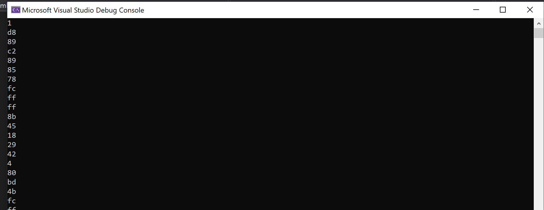
We can see that these opcodes line up with the values observed in x64dbg.
The add Instruction
Starting at the very top, we see that the first opcode is
0x01. Looking at our reference site here, we see that this is an
add instruction:
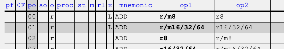
If we look in section 3.2 of the reference, we can see that this instruction adds a 32-bit register to a 32-bit register:

We still need to figure out how these registers are encoded, but for now,
we can modify our main loop to print out an
add instruction whenever we encounter 0x01.
Since we know that this instruction is 2 bytes, we will increment past the
next opcode when we encounter it as well. We can also add code to print
out the current address of the instruction:
while (i < START_ADDRESS + 0x50 - (DWORD)me32.modBaseAddr) {
  printf("%x:\t", i + (DWORD)me32.modBaseAddr);
  switch (buffer[i]) {
    case 0x1:
      printf("ADD ");
      i++;
      i++;
      break;
    default:
      printf("%x", buffer[i]);
      i++;
      break;
  }

  printf("\n");
}
When running this code, we will now see that the first add instruction is correctly disassembled:
Decoding Operands
After 0x01, the next opcode is 0xD8. We know
that this 0xD8 is somehow responsible for encoding the value
of eax, ebx. Just like with opcodes, the exact method to
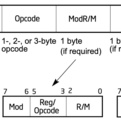
decode this value must exist somewhere in this manual. If we look at the
reference manual’s section 2.1, we see that directly following the opcode
is a ModR/M value that is 1 byte long:
If we scroll down to table 2-2, we can see how this value is laid out:
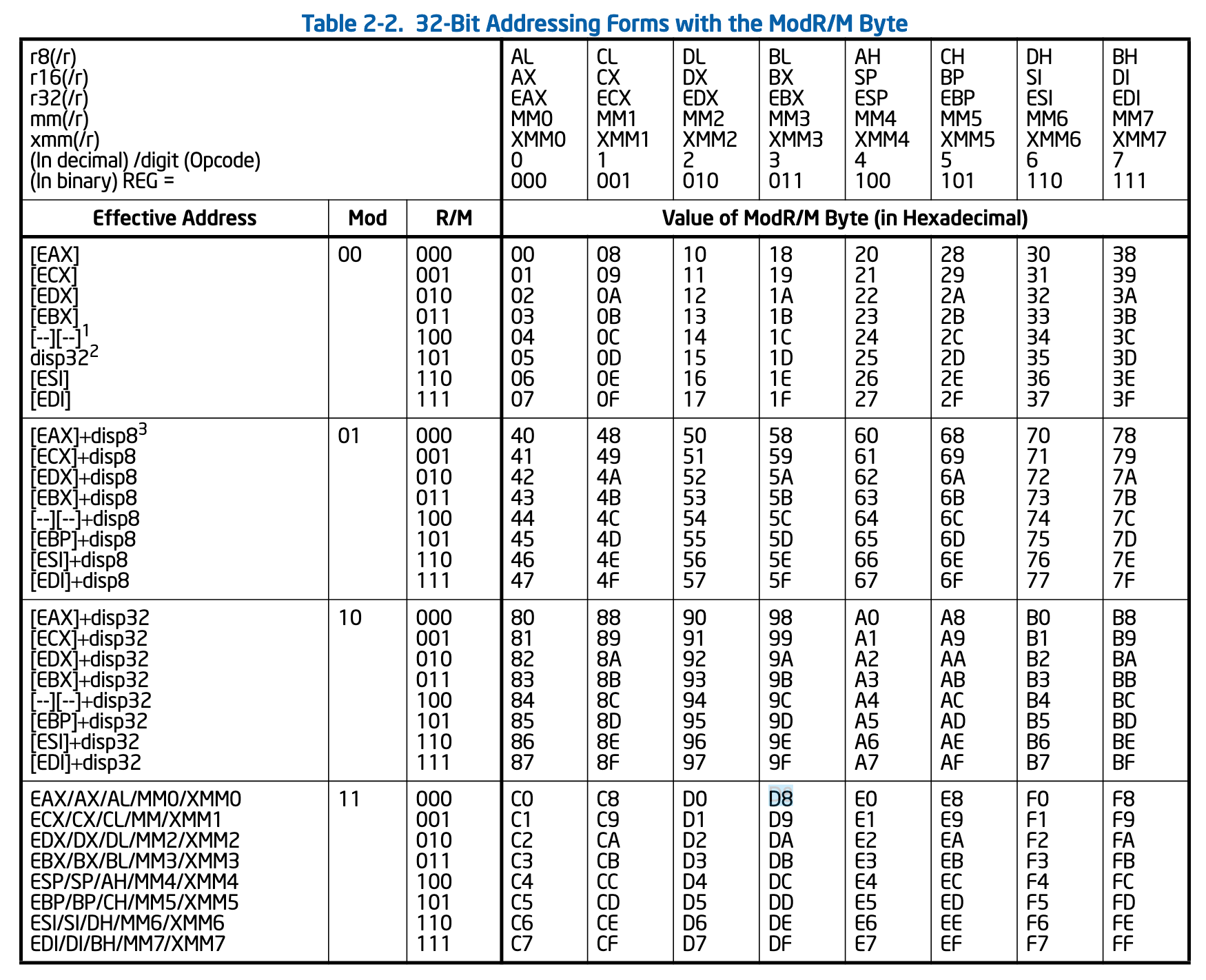
Finding the value of 0xD8, we see that it is in the
eax row and ebx column. Since this value
is stored in a consistent manner, we can write a function to retrieve it:
int decode_operand(unsigned char* buffer, int location) {

  return 1;
}
So far, we have seen that operands are 1 byte long, so we will return a value of 1 to correctly increment the loop. We can call this function from our main loop:
case 0x1:
  printf("ADD ");
  i++;
  i += decode_operand(buffer, i);
  break;
Going back to the table, we can see that we have 8 possible values: eax, ecx, edx, ebx, esp, ebp, esi, and edi. We can lay these out in an array of character arrays to reference in our function:
const char modrm_value[8][4] = {
  "eax",
  "ecx",
  "edx",
  "ebx",
  "esp",
  "ebp",
  "esi",
  "edi"
};
If we look at the table, we can see that eax will be the first operand whenever the byte value ends in 0 or 8:
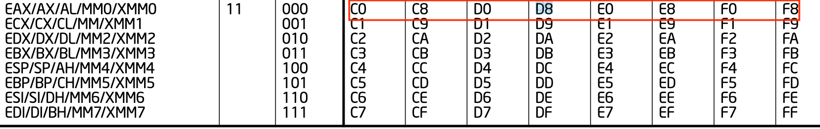
This pattern continues for the other registers as well. For example, ecx always ends in 1 or 9, and edx in 2 or A. We can see that these values line up with the remainder when we divide the operand value by 8. Therefore, we can use the modulo operator to retrieve our first operand from the ModR/M value:
modrm_value[buffer[location] % 8]
To retrieve the second operand, we can use a similar operation. If we look at the ModR/M structure, we can see that the first value is stored at bits 0, 1, and 2:
For example, when converted to binary, 0xD8 is represented
as:
1101 1000
For our first operand, we see that the three 000 bits are associated with the eax row. If we then shift these bits to the right, we get the following value:
0001 1011
If we look at the columns on the top of the table, 011 is associated with the ebx column, in the same way as the first operand. As such, we can use the same approach once we shift the bits to retrieve the second operand via the modulo operator:
modrm_value[(buffer[location] >> 3) % 8]
With these two pieces, we can implement our function:
if (buffer[location] >= 0xC0 && buffer[location] <= 0xFF) {
  printf("%s, %s", modrm_value[buffer[location] % 8], modrm_value[(buffer[location] >> 3) % 8]);
  return 1;
}
Running this code will correctly print the operands for the add operation:
Other Instructions
Now that we can disassemble the add instruction, we can
begin working on other instructions. First, let’s implement the
mov instruction at 0x7ccd93:
case 0x89:
  printf("MOV ");
  i++;
  i += decode_operand(buffer, i);
  break;
Running this, we can verify that our operand decoding is working
correctly, as 0xC2 (the operand associated with the second
move) correctly decodes to edx, eax:
However, the next mov instruction does not decode
correctly. Despite being the same opcode (0x89), it has an
operand that we have not seen before, 0x85. If we look at the
table, we see that this is associated with
[ebp] + displacement, or an offset. If we look at the
x64dbg version, we can see that this offset is -0x388. We
know that this value must be encoded somewhere in the instruction. Since
0x89 85 are already accounted for, this value must be in the
0x78fcffff bytes.
In previous lessons, we talked about endianness, or the order of bytes. We identified that bytes are stored in a little-endian format. As a result, we need to reverse these bytes:
FF FF FC 78
This value does not match 0x388. This is due to the signed
nature of the value. Since this is a negative value, we need to subtract
the maximum value of an integer (0xFF FF FF FF) to get the
correct value:
FF FF FF FF -
FF FF FC 78 =
387
We then need to add 1 to account for the sign change, resulting in the
correct value of -0x388.
Since we now understand how this is working, we can add this to our decode operation:
else if (buffer[location] >= 0x80 && buffer[location] <= 0xBF) {
  DWORD displacement = buffer[location + 1] | (buffer[location + 2] << 8) | (buffer[location + 3] << 16) | (buffer[location + 4] << 24);
  printf("[%s+%x], %s", modrm_value[buffer[location] % 8], displacement, modrm_value[(buffer[location] >> 3) % 8]);
  return 5;
}
Like we saw with the first decoding operation, we can use bit shifting to retrieve each of the bytes in the displacement. With this included, the third operation now correctly decodes:
Calls and Jumps
In previous lessons, we covered how the opcode for a call or jmp used the following formula:
E8/E9 (new_location - original_location + 5)
We can reverse this operation to retrieve the address of a call from an opcode:
case 0xE8:
  printf("CALL ");
  i++;
  loc = buffer[i] | (buffer[i+1] << 8) | (buffer[i+2] << 16) | (buffer[i+3] << 24);
  printf("%x", loc + (i + (DWORD)me32.modBaseAddr) + 4);
  i += 4;
  break;
We add 4 instead of 5 to account for the fact that our parser is past the
0xE8 byte.
We also have a short relative jump if equal (je) instruction in our selected example. In this case, we can observe that the second byte of the opcode contains the amount to offset by:
7ccda8    74 23   je 7ccdcd
7ccda8 + 23 = 7ccdcd
We can add this logic to our main loop as well:
case 0x74:
  printf("JE ");
  printf("%x", i + (DWORD)me32.modBaseAddr + 2 + buffer[i + 1]);
  i += 2;
  break;
Final Result
As stated in the disclaimer, this was not a comprehensive disassembler. In the source linked on github, the following opcodes are implemented:
- ADD (
0x01) - MOV (
0x89,0x8B) - SUB (
0x29) - JE (
0x74) - CALL (
0xE8) - CMP (
0x80) - LEA (
0x8D)
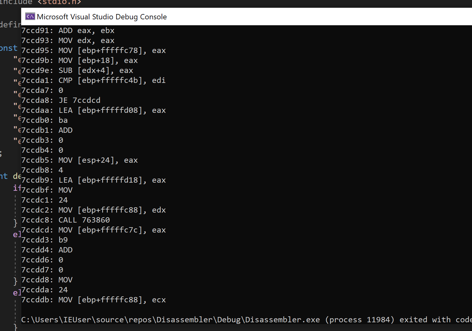
With these instructions, we retrieve back the following result: